Background: I installed a flagpole around 2001. The pole is aluminum but the mechanism had plastic bits. The plastic gradually wore out. A storm finally broke the very worn pieces. I can’t complain, it held up for 15 years.
What I did: In April I made my very first “invented from scratch & fully utilitarian” 3d print. I designed and printed replacements for the broken plastic bits. I was rather proud of myself. Was it worth the effort? I think so. I consumed a little over $4.50 in filament (counting an initial misprint). The equivalent parts would have cost $58 plus tax & shipping.
Nice start but…
…how has it worked out?
That’s what today’s post is about. I doubted my n00B 3d design skills were up to the task. I was right. There’s almost nowhere more extreme than the top of a flagpole in my homestead’s climate. A few months after installation a killer storm nuked one of the two parts I’d made. (It also knocked out the power for 15 hours!)
I’m not upset. Every failure is a lesson in how to improve.
Upon inspection, the part that broke had the stress of not just one flag but two. Makes sense that it gave out first.
The second observation is that it broke exactly where an experienced 3d guy would’ve predicted. I should have seen it coming!
3D printers lay down thin, precise, layers of filament. The layers fuse together to make the “in the round” object. Thus the term “fused filament fabrication” (FFF) or “fused deposition modeling” (FDM). This means 3D printed objects have planes of greater and lesser strength… just like wood.
[Warning: Rant Ensues:
For the few 3D naysayers out there “grain” is not a deal killer. FDM’s “grain” is very much like wood. All materials have good and bad characteristics (and sometimes the same characteristic is “good” or “bad” depending on what you’re making). Material properties are merely a fact of life, not a reason to ditch 3D.
Pine has grain. Vertical pine studs create strong walls. Horizontal pine studs aren’t strong enough. Pine logs, peeled and laminated, become plywood. Now it’s dimensionally stable on two planes but weak on the third. None of this is a flaw with wood (or FDM) it’s just details. For some reason this eludes anti-3d print people.
So long as I’m being grumpy, I also note people flake about 3D printing efficiency. It’s pretty high but some filament is wasted. Folks who shrug at a pile of chips under a CNC machine or the sawdust under a chainsaw, freak out when they learn a 3d printer “poops” waste when switching colors. I have no idea why.
Anyway, understanding “grain” in FDM is my idea of “fun”. It’s rising to the real world from the “frictionless constant” of theory. Forgive me if I’m preaching to the choir. I’m sure similar things were said by the first guy that rolled a Model T through town in a time of horses.
/Rant off.]
Anyway, here’s an excerpt from the April post:
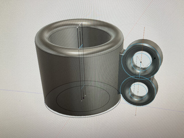
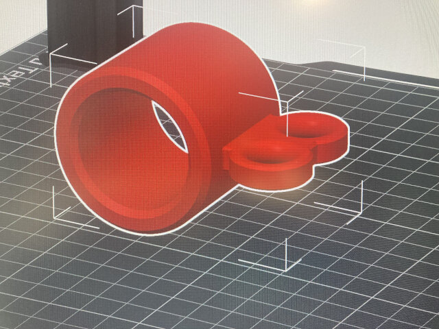
…the “middle anchor” …has two anchor points. Here it is in Fusion 360.
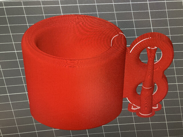
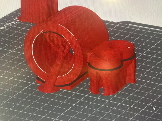
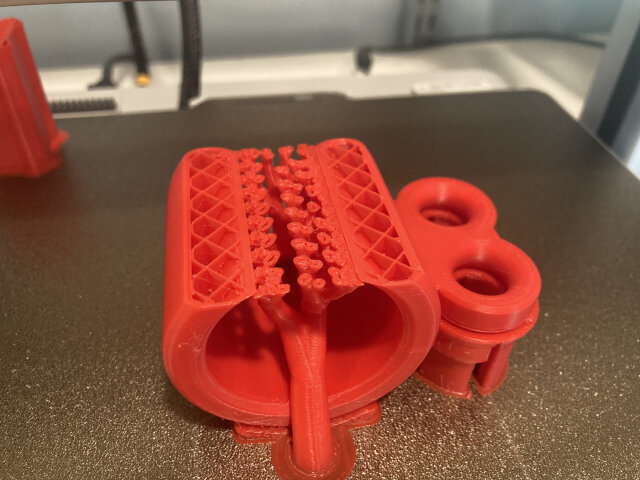
Here it is in the slicer. (Notice the “tree” supports that hold up the “overhang” on the two loops.)
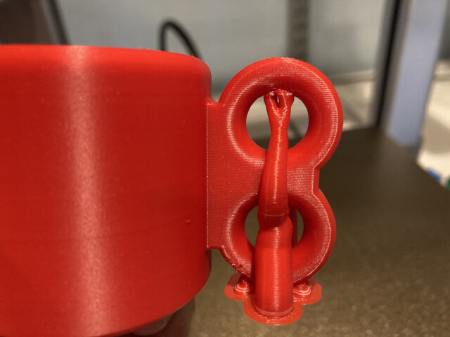
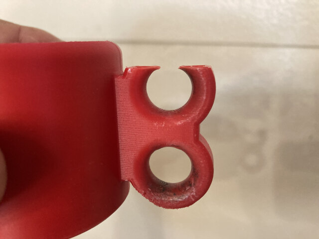
Here it is in real life.
Do you see my mistake? In retrospect it’s obvious! I carefully aimed to reduce support material. (That “efficiency” thing again. Reduced support means the object consumes less filament during printing.) Printing in that orientation didn’t address “grain”.
Based on the use, where would be the most stress? On the top loop where it’s anchored to the highest flag. Where’s the weakest point of a stack of horizontal layers? On the top of the top loop.
Where did the object break? On the top loop; right where it’s weakest. Duh!
Life is more interesting in the real world. There’s always something you didn’t anticipate.
[At this point I turned my garage inside out looking for the broken part to illustrate the situation. I couldn’t find it. THIS ALWAYS HAPPENS WHEN I CLEAN MY GARAGE! Then I found the broken part still on the flagpole. I apologized to the garage.]
Here’s the image. It snapped like a knife cut it:
I could make an improved design, but I decided not to do that. I got excited about a “controlled experiment”!
I pulled up the old file and loaded the rest of the same spool of PETG. I setup a print of the exact same object changing only the orientation. My plan is to put the new object back up the exact same flagpole. Accepting the caveats of unpredictable storms and seasonal variation, I’ll see how long the object lasts with nothing changed but the “grain”.
Place your bets!
Another image, this time with supports. (The black layer is PLA plastic which doesn’t adhere to the red PETG. This makes it easy to snap off the supports.)
Dammit! I fucked up.
I changed orientation and hit print. Seems logical but I forgot a detail. In mid-print I realized I’d left “infill” on default (I think it’s 10%).
Just about any solid made from a 3d printer is partially void. Plastic is strong enough to do internal voids so why wouldn’t you use that feature? (Note: This is not possible with casting, injection molding, or milling.)
Did I do that last time? Nope! Here’s my own text from last time:
I made it thicker, beefed up the infill and other slicer settings, and so forth. I think it looks better than store bought.
My new print with only 10% infill (90% of the object’s volume is void) is going to be shit! My “controlled experiment” was officially the same level bullshit as the media reporting the newest thing that cures cancer in rats!
Rather than give up I decided to burn money (actually filament and not much at that) to learn. (Is not learning the whole point?)
I made it again. Still the same model, still horizontal orientation, but this time with 50% infill and I switched from boring “grid” infill to snazzy “gyroid”. There are mathematically inclined nerds who spent their life on these patterns. If awesome gyroid infill is an option, it only seems logical to try it.
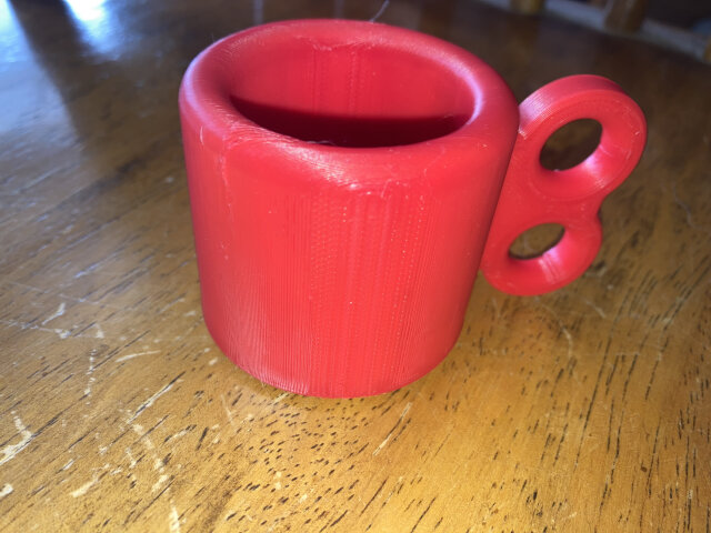
Here’s the finished product (of course you can’t tell the kind of infill by just looking at it):
 Just for fun I “destructive tested” the 10% infill, horizontally printed object. I twisted it by hand. Indeed it snapped along the different “grain”, just as it should. In this case, I’m not sure the weakness matters. There would be a flagpole in the center so the torsion I applied by hand would be impossible. Maybe I’m overthinking it?
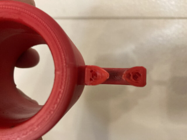
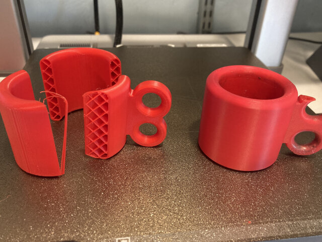
I took a photo of the two broken parts, to compare how they broke. The right broke in real life over months and the on on the left was mangled by it’s creator for fun. Maybe I should read Frankenstein again?
As soon as the horizontally oriented, 50% infill object came off the printer, I hoisted the flag. There’s no better test than the real world.

A sailor’s solution, Fig’s 84-86:
https://l-36.com/knots_splices_ropework.php?chapter=5
Ha ha ha… sailors can do anything involving a pole and a flag. That’s their thing.
Glad to have you back poasting and toasting.
The old-skool ropework is conducive to hours in front of a muttering and ticking stove. The stove is useful for storing interim stages of the project that fail quality inspection by the canine destructive testing unit (K9DTU). This automatic device must however be calibrated and lubricated at regular intervals, allegedly using bacon and beef bones if the self generated user guide is to be believed.
Fantastic experiment. Having done some printing within the College environment, if your results require further improvement, try filling in the curves between the upper loop and the body. Also, bump the infill up to 100%. We used to do that on parts put into actual usage in machines. Good luck.